-
Contact
|
-
Wechat
Wechat:tel-15397675238Scan Contact
|
 CHINESE |
 Русский язык
Wechat:tel-15397675238Scan Contact
CHINESEРусский язык
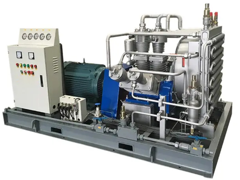
1. Medium composition: air
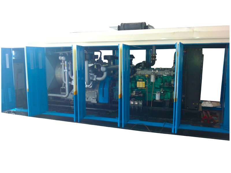
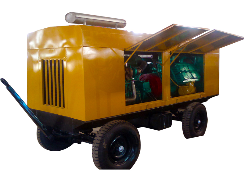
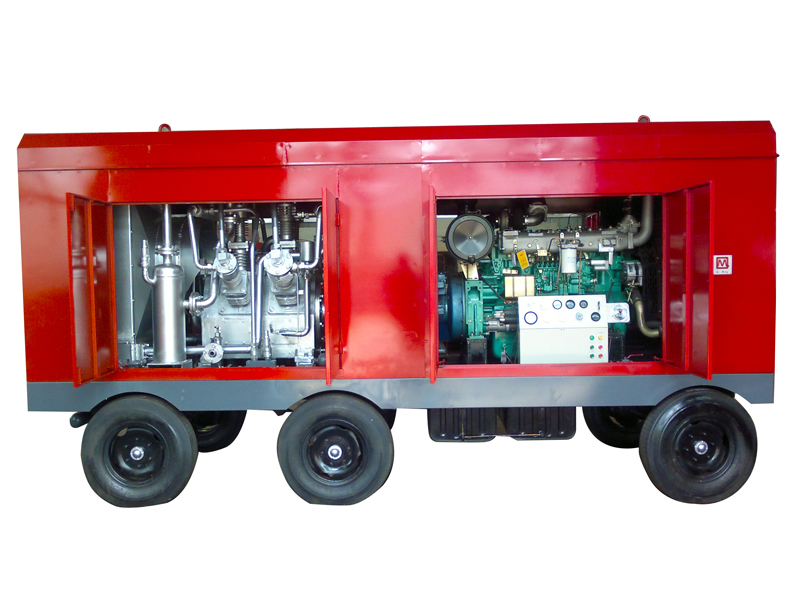
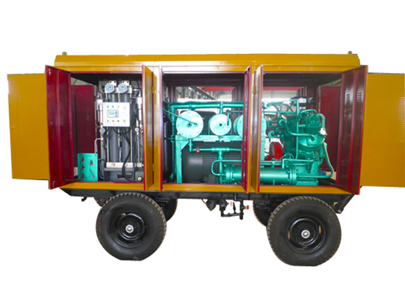
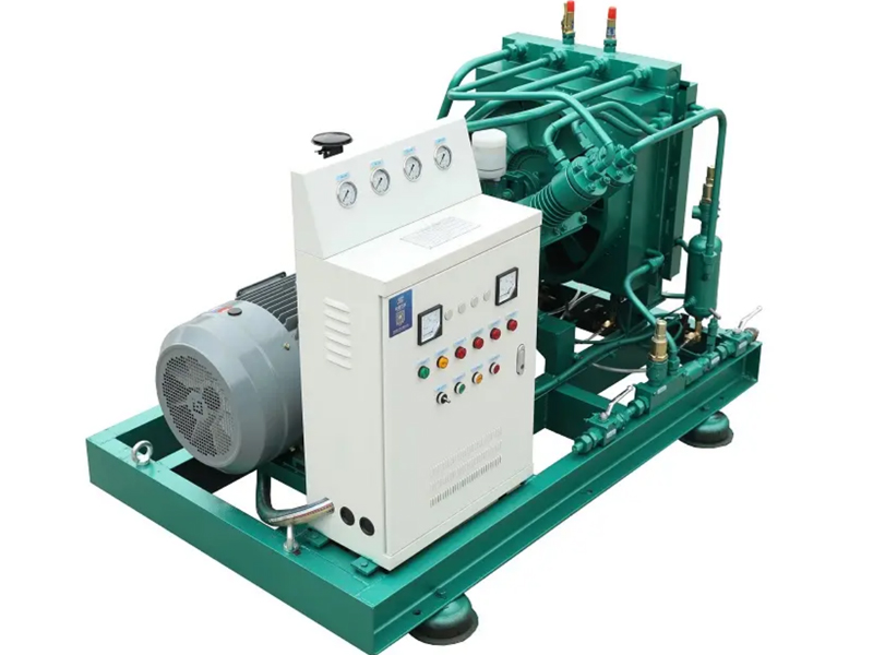
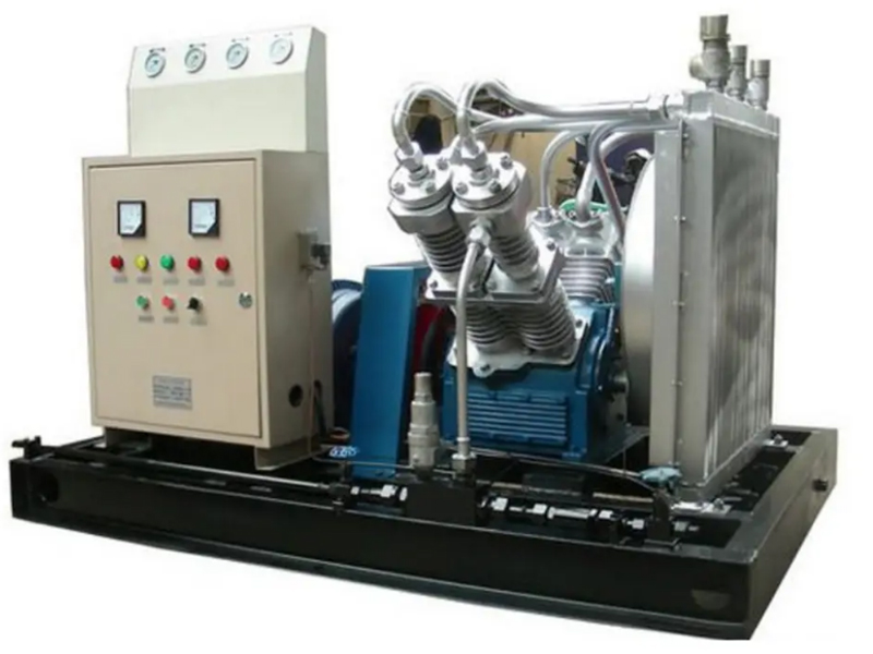
2. Compressor Model: SF-10/250CY Diesel Mobile Air Compressor
3. Structural form: S-shaped, air-cooled
4. Compression stages: Four-stage compression
5. Cylinder diameter for each grade (mm): Grade 1: Φ260×2, Grade 2: Φ140×2, Grade 3: Φ70×2, Grade 4: Φ35×2
6. Nominal volumetric flow rate (m³/min): 10
7. Inhalation pressure: MPa(G): Atmospheric pressure
8. Exhaust pressure: MPa(G): 25.0
9. Inhalation temperature (°C): ≤40
10. Gas supply temperature (°C): ≤180
11. Compressor speed (r/min): 1150
12. Transmission method: Hydraulic clutch connection, speed ratio: 1:1.3
13. Lubrication method: Combined lubrication of oil pump and splash lubrication
14. Installation method: mobile, with cover.
15. Lubricating oil consumption: 120g/h
16. Noise dB(A): ≤104
17. Powertrain: Yuchai YC6M350-D20 258.5KW 1500r/min
18. Stroke: 120mm
19. External dimensions (length × width × height) mm: Approximately 5000 × 1900 × 2600
20. Weight (kg): Approximately 5500
Price: 10,000 (inclusive of tax and shipping).
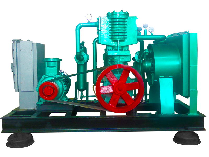
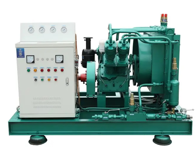
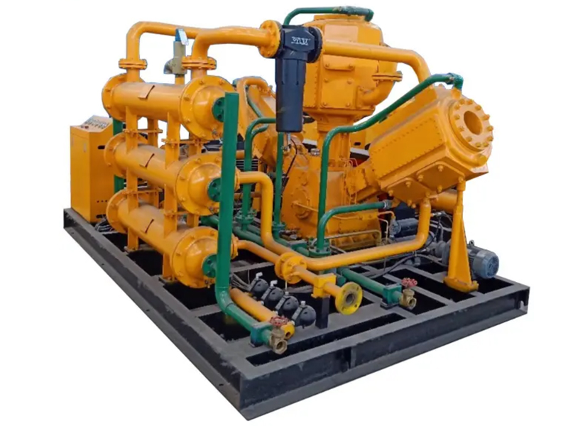
II. Compressor Main Unit
1. Crankcase components:
The crankcase has side covers and oil sight glasses on both sides for disassembly and inspection. The front section, which is the power connection end, is equipped with a bearing housing and a front bearing cover. The fan bracket on the upper part of the rear bearing cover supports the fan assembly. The upper part is cast with cylinder support planes at 45 degrees to each other. The larger side is equipped with the first-stage cylinder assembly, and the smaller side is equipped with the second-stage cylinder assembly. The top surface is equipped with a breather. The bottom of the crankcase is equipped with an oil pan, which contains special compressor oil.
2. Crankshaft, connecting rod and components
The crankshaft has connecting rods mounted on its crankshaft, rolling bearings at both ends, a flywheel at the large end connected to a flexible coupling, and a pulley near the bearing at the small end to drive the cooling fan. Lubrication of the crankshaft is achieved by the oil spray from the connecting rod's oil rod onto the crankshaft and piston pins, among other components.
3. Piston assembly:
The piston assembly consists of four stages: primary, secondary, tertiary, and quaternary. The primary piston is made of cast aluminum alloy, the secondary piston is cast iron, the tertiary piston is cast aluminum alloy, and the quaternary piston is made of 45# steel. Both primary and secondary pistons are fitted with piston rings: a flat ring at the top, a torsion ring in the middle, and an oil ring at the bottom. The oil scraper ring opening is offset from the piston pin hole by more than 60 degrees, and the openings of all piston rings are offset from each other by 120 degrees. The tertiary stage has 7 flat rings, and the quaternary stage has 11 flat rings.
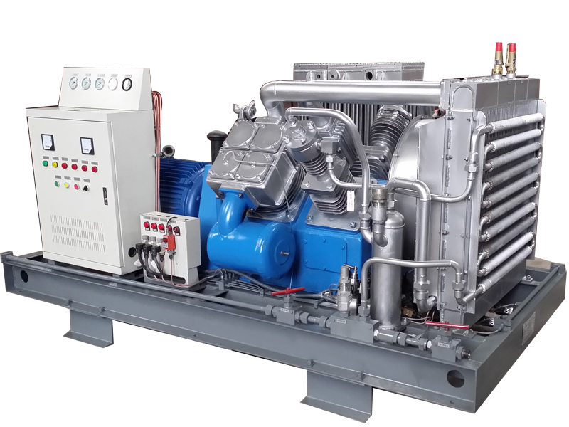
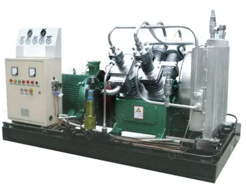
4. Cylinder components:
The cylinder components are divided into first-stage, second-stage, third-stage, and fourth-stage cylinders. The cylinder heads of the first-stage, second-stage, third-stage, and fourth-stage cylinders are all cast with cooling fins to increase the heat dissipation area. The cylinder heads are equipped with intake and exhaust valve components, intake and exhaust pressure cylinders, and intake and exhaust pressure caps, respectively.
5. Intake and exhaust valve components:
The system consists of a primary intake valve, a primary exhaust valve, a secondary intake valve, and a secondary exhaust valve, all of which are annular valve structures. The valve seat has a spring supporting the annular valve plate, and both the valve plate and the spring are made of high-quality steel. The tertiary and quaternary stages are combined intake and exhaust valves.
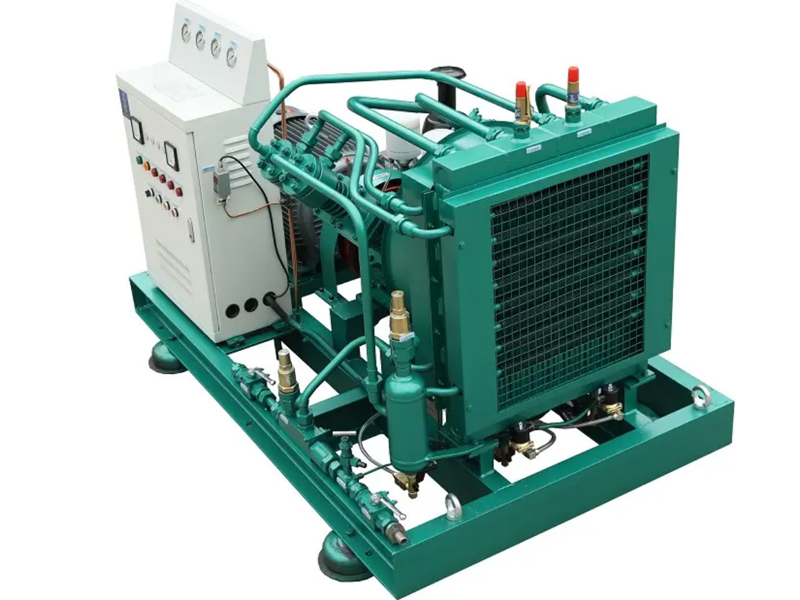
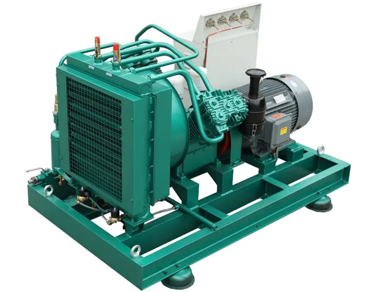
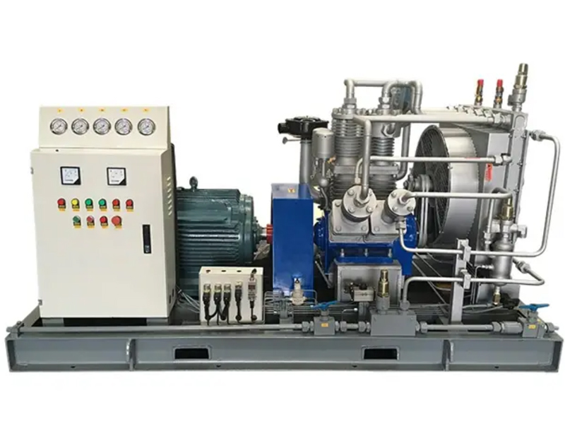
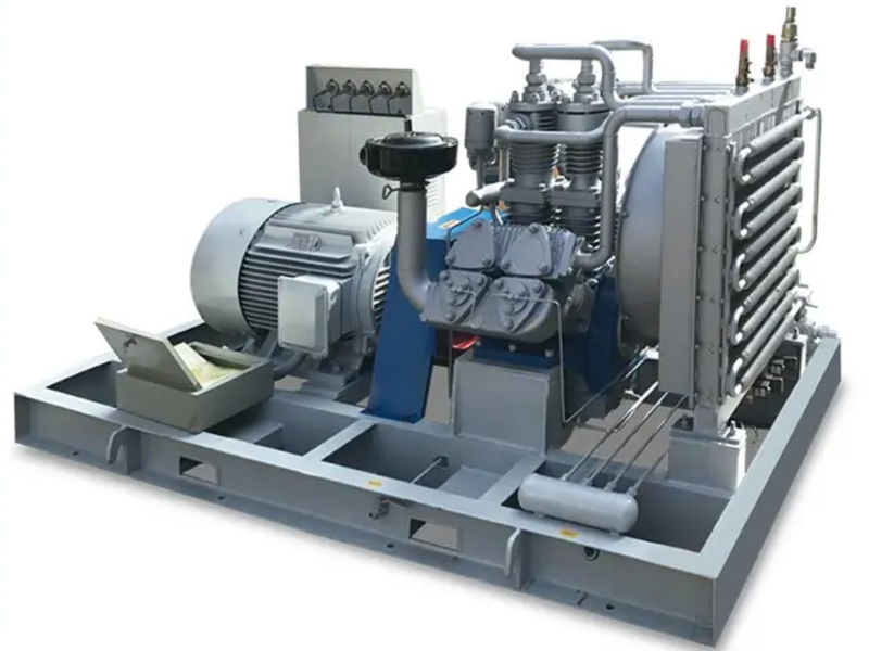
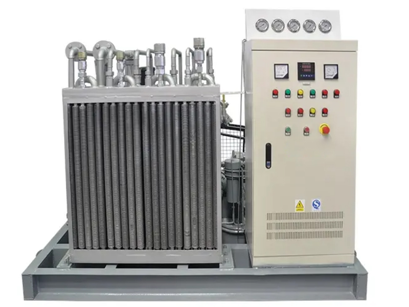
6. Cooler and fan components:
It consists of three stages: a primary, secondary, and tertiary cooler, and a cooling fan. It connects to the intake and exhaust ports of the primary, secondary, and tertiary stages of the compressor. Mounted on a base by uprights, the cooler has a safety valve at the top and a solenoid drain valve at the bottom. A guide cover and protective cover are installed facing the crankcase. A fan-type cooling fan is mounted in the middle, with a fan bracket supporting the fan assembly on the crankcase. The fan is driven by a crankshaft pulley at the end of the crankcase via a V-belt.
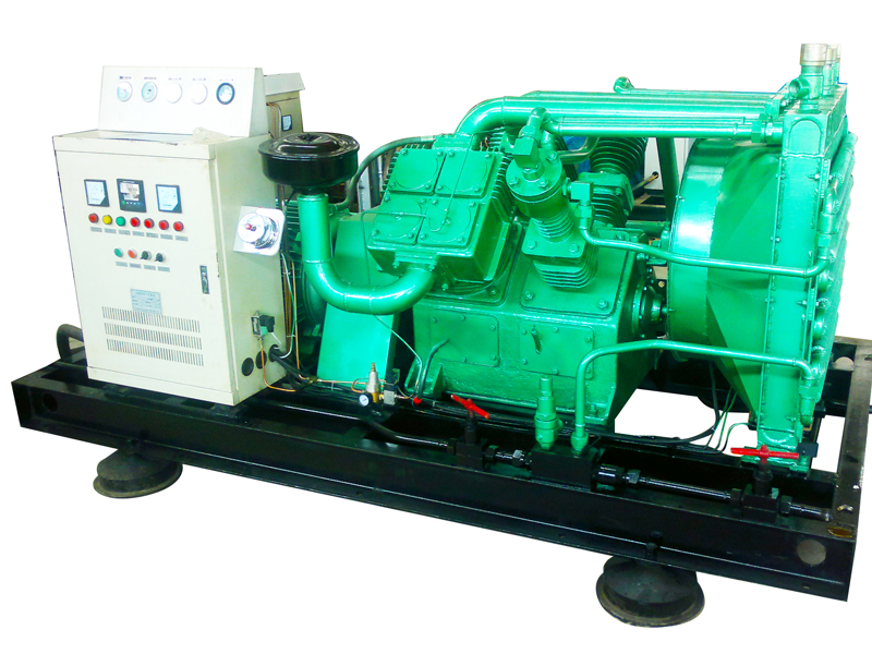
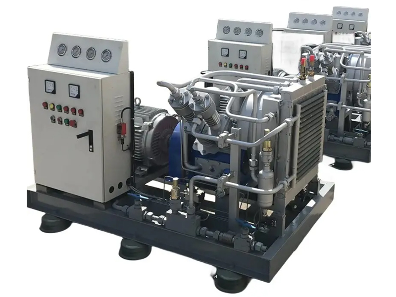
III. Compressor Control System
1. The instrument panel is equipped with pressure gauges of levels one, two, three, and four, compressor oil temperature gauge, diesel engine tachometer, etc.
2. The compressor will automatically shut down when the discharge pressure is high.
3. Pressure control at each stage of the compressor, and unloading at the pressure limit.
4. Electromagnetic automatic sewage discharge and manual sewage discharge.
5. Lubrication System: The air compressor uses a combination of oil pump and splash lubrication. Oil splashes throughout the housing, forming an oil mist that effectively lubricates bearings, pistons, piston rings, and other moving parts. The oil pump supplies oil to lubricate the crankshaft bearings.
Contact
15397675238
Email:hc689com@163.com
Phone:15397675238
Tel:+8615397675238
Address:No. 1360 Jiushi Road, Luzhou, Chuannan Port Area, Sichuan Free Trade Zone
![[field:title/]](https://www.hc986.com/static/upload/image/20250127/1737955113187381.jpg)
![[field:title/]](https://www.hc986.com/static/upload/image/20250127/1737955364387567.jpg)